This document is a user guide for quick start. With a few examples listed, the user will be familiar with this timing diagram generator tool, timing-gen.
1. Clock
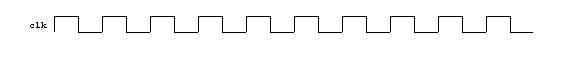
A clock is a good place to start. Here is a "hello World!" type diagram.
Here is the input file.
@Waves =
  (
   {type  => clock,
    name  => clk
   }
  );

1;
Timing-gen generates 10 cycles in 6.5 inch span as its default. A clock is specified by setting type parameter to clock in @Waves variable. You specify The signal name with name parameter. You can use just about any printable characters if you quote the name value.
The last line "1;" is something you have to have in every timing-gen input file.
2. Counter
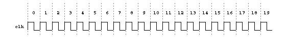
Let’s add more cycles by adding %Conf variable. Also we will add a cycle counter and cycle bars to make the diagram easy to read.
Here is the input file.
%Conf =
  (
   cycles => 20,
  );


@Waves =
  (
   {type  => counter
   },

   {type  => clock,
    name  => clk
   },

   {type  => bar,
   }
  );

1;
The number of total cycles is specified with cycles parameter in %Conf variable. %Conf is where you specify global configuration. Notice that timing-gen generates the output in the same width as before. It calculates width of each cycle from the drawing width and the number of cycles.
The bar type adds cycle bar or cycle divider with dashed lines.
3. Signal
You can add a single bit signal by setting type parameter to bit. You can also add a multi-bit signal by setting type parameter to bus. One of the differences between bit and bus is that a bit can only show high and low state in the diagram while a bus can show a value.
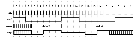
A parameter called change is defined in all bit and bus signals. This specifies cycles and values of value changes in pairs. The first number of a pair is the cycle number that the signal changes the value to the second number.
%Conf =
  (
   cycles => 20,
  );


@Waves =
  (

   {type  => counter
   },

   {type  => clock,
    name  => clk
   },

   {type  => bit,
    name  => 'cs#',
    change => [ [0,1], [2,0], [8,1],  [11,0], [17,1] ],
   },

   {type  => bus,
    name  => 'data',
    change => [ [0,'-'], [3,'data0'], [8,'Z'],  [12,'data1'], [17,'Z']],
   },

   {type  => bit,
    name  => 'oe#',
    change => [ [0,'X'], [3,0], [5,1], [8, 'Z'],  [12,0], [14,1], [16,'-'] ],
   },

   {type  => bar,
   }
  );

1;
As you may have guessed already, you specify the signals in the sequence you want them to show up.
X or U (undefined) show up a cross pattern. - (dontcare) shows up a diagonal pattern.
4. Slew
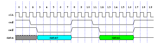
You can change slew rate with slew parameter in %Conf. When the value is larger, the signal changes slower. 0 means that the signal changes instantly.
Note that slew is one of configuration keys that the value is not based on a percentage of cycle period (such as delay) but a fixed size. This is to keep the same angle regardless of the total number of cycles.
%Conf =
  (
   cycles => 20,
   delay  => 0.1,
   slew   => 3,
   slew_offset   => 1,
  );


@Waves =
  (

   {type  => counter
   },

   {type  => clock,
    name  => clk
   },

   {type  => bit,
    name  => 'cs#',
    change => [ [0,1], [2,0], [8,1],  [11,0], [17,1] ],
   },

   {type  => bit,
    name  => 'oe#',
    change => [ [0,1], [3,0], [8,1],  [12,0], [17,1] ],
   },

   {type  => bus,
    name  => 'data',
    change => [ [0,'X'], [3,'data0',{fill_color=>3}], [8,'Z'],  [12,'data1',{fill_color=>2}], [17,'Z'] ],
   },

   {type  => bar,
    conf  => {color=>1},
   }
  );

1;
A little bit of colors won’t hurt. (A lot of color can!) In the bar, color is set in conf parameter. color configuration key specifies the line (outline) color. In data signal, fill_color are set in two different cycle-value pair. fill_color key specifies the color to fill the area. You can specify a signal wide fill_color, instead of individual cycles, by using conf parameter, for example, conf \=\> {fill_color\=\>5}.
<HR>
5. Measure
Measure type is used to specify the span of timing parameters, such as setup time or hold time.

The list parameter in measure can have arbitary number of timing parameter measures. They all shows up on one row. If you want timing measures on a different row, define another measure type. measure type honors the appearance sequece as bit and bus do. So if you want a maasure above a signal, define the measure above the signal.
%Conf =
  (
   cycles => 20,
   delay  => 0.1,
   slew   => 3,
   slew_offset   => 1,
  );


@Waves =
  (

   {type  => counter
   },

   {type  => clock,
    name  => clk
   },

   {type  => bit,
    name  => 'cs#',
    change => [ [0,1], [2,0], [8,1],  [11,0], [17,1] ],
   },

   {type  => bit,
    name  => 'oe#',
    change => [ [0,1], [3,0], [8,1],  [12,0], [17,1] ],
   },

   {type  => blank,
   },

   {type  => bus,
    name  => 'data',
    change => [ [0,'X'],  [3, 'data0',{fill_color =>3}],
                [8,'Z'],  [12,'data1',{fill_color =>13}],
                [17,'Z'] ],
   },

   # block title
   {type  => blank,
    name  => 'cpu_block',
   },
   {type   => text,
    conf   => {font_size=>14, justify=>0, text_y=>0.3},
    point  => [cpu_block, 0],
    text   => 'CPU',
   },

   # measure
   {type  => measure,
    list  => {'setup' => [ [clk,7], [cpu_d0] ],
              'max prop delay' => [ [data,12], [cpu_d1] ],
             },
   },

   {type  => bus,
    name  => 'data at CPU',
    change => [ [0,'Z'],
                [5, 'data0',{delay=>0.5, id=>cpu_d0}],
                [7, 'Z',    {delay=>0.3, id=>cpu_d0e}],
                [14,'data1',{delay=>0.5, id=>cpu_d1}],
                [16,'Z',    {delay=>0.3}] ],
   },

   {type  => measure,
    list  => {'hold'  => [ [clk,7], [cpu_d0e] ],
             },
   },

   # vertical bars
   {type  => bar,
    conf  => {color=>44},
    point => [0..19],
   }
  );

1;
In cycle 5 of data at CPU, there are delay and id configuration keys. delay adds signal delay from clock edge. You can specify this key in conf parameter if you want signal common delay. You can specify the key in %Conf variable as a global configuration to have all signals delayed.
A global configuration can be overridden by a signal conf parameter, which can be overriden by a cycle configuration key. This hiearchical configuration system gives you the maximum flexibiity without being verbose.
Configuration key id is anothe handy feature. It names that the particular signal and the cycle. Then the name (ID) can be used in measure and arrow. This is helpful when you add or delete some cycles. The IDs stays where it is defined so you don’t have to change all measures and arrows. Just like a signal name, ID value can be just about any printable characters including spaces if you quote them.
6. Arrow
Arrow type is used to show cause-and-effect relationships, such as request-and-acknowledge or output_enable-to-data_output.
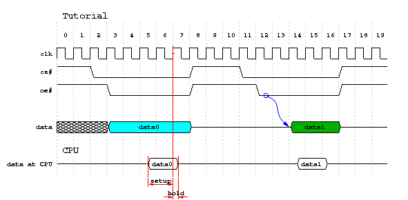
An arrow is added in this example, from oe# cycle 13 to data 14, to show that oe# is gating data bus (with some delay).
%Conf =
  (
   cycles => 20,
   delay  => 0.1,
   slew   => 3,
   slew_offset   => 1,
  );


@Waves =
  (

   {type   => blank,
    name   => title,
   },

   {type   => text,
    conf   => {font_size=>14, justify=>0, row_y=>-1},
    point  => [title, 0],
    text   => 'Tutorial',

   },

   {type  => counter
   },

   {type  => clock,
    name  => clk
   },

   {type  => bit,
    name  => 'cs#',
    change => [ [0,1], [2,0], [8,1],  [11,0], [17,1] ],
   },

   {type  => bit,
    name  => 'oe#',
    change => [ [0,1], [3,0], [8,1],  [12,0], [17,1] ],
   },

   {type  => blank,
   },

   {type  => bus,
    name  => 'data',
    change => [ [0,'X'],  [3, 'data0',{fill_color =>3}],
                [8,'Z'],
                [14,'data1',{fill_color =>13, id=> data1_0}],
                [17,'Z'] ],
   },

   # block title
   {type  => blank,
    name  => 'cpu_block',
   },
   {type   => text,
    conf   => {font_size=>14, justify=>0, text_y=>0.3},
    point  => [cpu_block, 0],
    text   => 'CPU',
   },


   {type  => bus,
    name  => 'data at CPU',
    change => [ [0,'Z'],
                [5, 'data0',{delay=>0.5, id=>cpu_d1}],
                [7, 'Z',    {delay=>0.3, id=>cpu_d2}],
                [14,'data1',{delay=>0.5}],
                [16,'Z',    {delay=>0.3}] ],
   },

   # measure
   {type  => measure,
    list  => {'setup' => [ [clk,7], [cpu_d1] ],
             },
   },

   {type  => measure,
    list  => {'hold'  => [ [clk,7], [cpu_d2] ],
             },
   },

   # arrow
   {type  => arrow,
    name  => a_1,
    point => [['oe#', 12], [data1_0]],
   },

   # vertical bars
   {type  => bar,
    conf  => {color=>44},
   }
  );

1;
arrow type requires a point parameter, which specifies its starting point and ending point. Starting point and ending point can be specified in 2 ways. One is signal name and cycle number pair. The starting point of arrow a_1 is [oe#, 12] in the above code. The other way is an ID. ID is a name that is defined in a signal cycle. data1_0 used in arrow a_1 is defined in signal data cycle 14. This method is preferred because the arrow point will stay with the change event of the signal, even if you moved the cycle number, or even if you changed signal name.